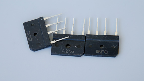
Principle and function of bridge rectifier
2021/6/25
There are many types of bridge rectifiers: flat, round, square, bench-shaped (in-line and patch), etc., and there are GPP and O/J structures. The larger rectified current ranges from 0.5A to 100A, and the higher reverse peak voltage ranges from 50V to 1600V.
The half bridge is to seal the half of the two diode bridge rectifiers together. Two half bridges can form a bridge rectifier circuit, and a half bridge can also form a full-wave rectifier circuit with a center tap of the transformer.
When choosing a rectifier bridge, the rectifier circuit and operating voltage must be considered.
The rectifier bridge stack is generally used in a full-wave rectifier circuit, and it is divided into a full bridge and a half bridge.
The full bridge is composed of 4 rectifier diodes connected in the form of a bridge full-wave rectifier circuit and packaged as a whole.
The forward current of the full bridge has various specifications such as 0.5A, 1A, 1.5A, 2A, 2.5A, 3A, 5A, 10A, 20A, 35A, 50A, etc. The withstand voltage (reverse voltage) is 25V, 50V, 100V , 200V, 300V, 400V, 500V, 600V, 800V, 1000V and many other specifications.
The role of bridge rectification
1. Convert the alternating current generated by the alternator into direct current to supply power to the electrical equipment and charge the battery;
2. Limit the battery current to flow back to the generator to protect the generator from being burnt out by the reverse current.
Application of bridge rectifier
The bridge rectifier circuit overcomes the shortcomings that the full-wave rectifier circuit requires the transformer secondary to have a center tap and the diode to withstand large back pressure, but two more diodes are used. With the rapid development of semiconductor devices and low cost today, this shortcoming is not prominent, so bridge rectifier circuits are widely used in practice.
It needs to be pointed out that the diode as a rectifier component should be selected according to different rectification methods and load sizes. If you choose improperly, you may not be able to work safely, or even burn the pipe; or you may be overkill and cause waste.
Principle of bridge rectifier circuit
The bridge rectifier circuit can also be considered as a kind of full-wave rectifier circuit, with four diodes connected to the transformer windings. D 1 to D 4 are four identical rectifier diodes connected in the form of a bridge, so they are called bridge rectifier circuits. Using the guiding function of the diode, the secondary output can be directed to the load even in the negative half cycle. In the positive half cycle, D1 and D2 guide the current through RL from top to bottom, and in the negative half cycle, the current is guided by D3 and D4 through RL from top to bottom, thus realizing full-wave rectification. In this structure, if the same DC voltage is output, the secondary winding of the transformer needs only half of the winding compared with the full-wave rectification. However, if the same amount of current is to be output, the diameter of the winding should be thickened accordingly. As for the pulsation, it is exactly the same as the full-wave rectifier circuit mentioned above.
Because the output voltage of the rectifier circuit contains larger pulsating components. In order to reduce the pulsation component as much as possible, on the other hand, it is necessary to keep the DC component as much as possible to make the output voltage close to the ideal DC. This measure is filtering. Filtering is usually achieved by using the energy storage effect of capacitors or inductors.
Huangshan City Zhen Yi Electronics Co.,Ltd. All rights reserved 皖ICP备12019564号 Disclaimer

